

|
|

 |
||||||||||||||||||||||||||||
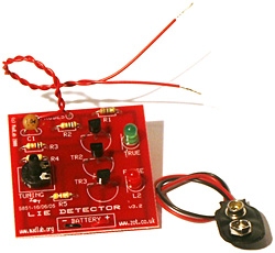
Lie Detector The circuit diagram of the Lie Detector is shown below. It consists of three transistors (TR1 to TR3), a capacitor (C1), two lights or LEDs (L1 & L2), five resistors (R1 to R5), and a variable resistor (VR1). Suitable transistors to use are BC547, BC548 or BC549, or any other small NPN transistor. This circuit is based on the fact that a person's skin resistance changes when they sweat (sweating because they're lying). Dry skin has a resistance of about 1 million ohms, whereas the resistance of moist skin is reduced by a factor of ten or more. Resistors R1 and R2 form a voltage divider. They have resistances of 1 000 000 ohms (1 mega ohms) and, because their values are equal, the voltage at the upper probe wire is half the battery voltage (about 4.5 volts). A person holding the probe wires will change the voltage at the upper probe wire depending on their skin resistance. The skin resistance is in parallel with R2 and, because it is likely to be similar to or smaller than R2, the voltage at the probe wire will fall as skin resistance falls. Capacitor C1 functions as a smoothing capacitor and removes the 50Hz induced mains hum that is found on a person's body. TR1 and R3 form a buffer circuit (called an emitter-follower). The voltage at the emitter of TR1 follows the voltage at the probe wire and is now able to drive transistor TR2. Transistors TR1 and TR2 act as a voltage comparator. If the voltage at the base of TR2 is higher than at the base of TR3 then the green LED (L1) will come on. If the reverse is true then the red LED (L2) will light. To test the Lie Detector hold the probe wires. Adjust VR1 until the green LED is just on and the red LED is just off. This is the point at which the voltage at the base of TR2 is just greater than at the base of TR3. Now use moist fingers to hold the probes. This lowers the skin resistance and causes the voltage at the base of TR2 to fall. The voltage at the base of TR3 is now greater and the red LED comes on. 
This kit is available in Europe from
Velleman MadLab kits are also available in America from Fry's and Jameco as well as other suppliers. For educational orders for schools, colleges and festivals, please email. Construction Sheet | Order Form |
||||||||||||||||||||||||||||
|
||||||||||||||||||||||||||||